The WizYasep board
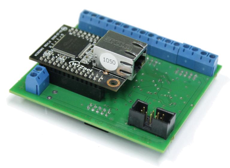
The WizYasep is an an electronic circuit board that YGDES designed to transmit and transcode data flows through Ethernet, at high speed, low latency and low jitter. Its first purpose is the control of networked LED screens but its simplicity, performance and versatility make it ideal for many industrial, embedded and real-time applications.
WizYasep is created and developed in France by YGDES, reusing tools from the YASEP project, and it is assembled in France by Dipole Electronique.
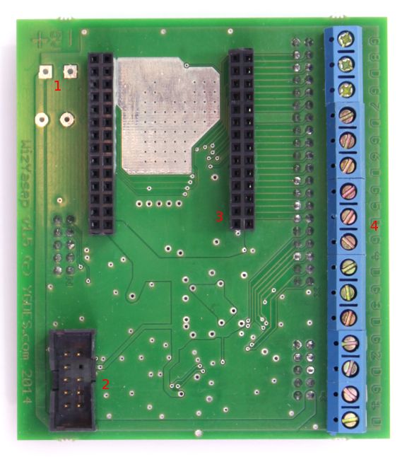
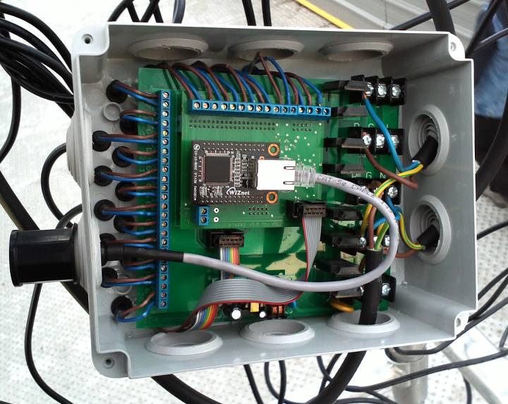
1 : 5V input
2 : JTAG (reconfigure the FPGA)
3 : Wiznet module header
4 : 8 digital outputs
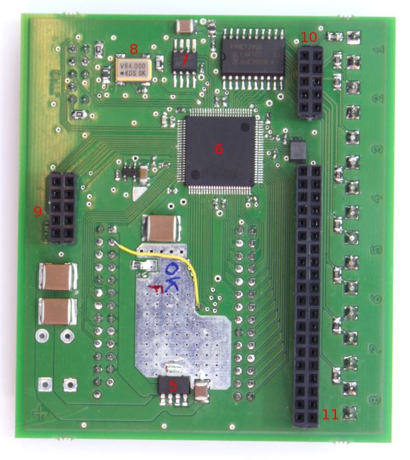
5 : Low-drop 3.3V regulator
6 : FPGA (A3P250-VQ100)
7 : SPI Flash memory
8 : 64MHz canned oscillator
9 : Z header (console)
10 : Y header (8 5V outputs)
11 : X header (GPIO, 16 bits bus)
The Wiznet combines a non-volatile FPGA and a Wiznet module with hardwired TCP/IP stack to overcome the inherent limitations of classic sequential microcontrollers or microprocessors. At power-up, the board is immediately functional because there is no operating system. Hardwired, parallel features also garantee extremely short and stable timings: the Wiznet controller's ping round trip time is only 0,1ms through one hub, 7× faster than a Raspberry Pi.
The FPGA processes many simple logic computations in parallel, which removes the bottleneck of serial execution, inherent with computer programs. A lot of time is usually spent by a CPU just moving data around. A FPGA provides short and deterministic results, making it ideal for hard real time applications.
The PLL can increase or decrease the 64MHz clock.
The Wiznet module can handle up to 8 simultaneous IP sockets. Its internal buffer can hold 128Ki bytes of received or sent data, enabling us to work with much larger datasets than other solutions (the widespread W5100 can hold much less data). The 16-bits parallel data bus reads or writes the buffers at 18MB/s, twice as fast as the network speed.
The FPGA is an extremely flexible circuit: it can work with several clock domains, it can process many logic computations in parallel and any pin can be allocated for any purpose. You won't need to change the board, like when your microcontroller doesn't have the right set of I/O and peripherals! The WizYasep adapts to the project, not the reverse.
The headers are used for factory testing, development, configuration and updates, as well as for extensions. The "bare" WizYasep board provides only 8 buffered digital outputs, to directly drive 8 LED strings. These buffered signals are also available on the Y header if you need a different connexion.
The Z header provides 8 other GPIO, though these pins are shared with the "console" (asynchronous and synchronous serial communications with the FPGA and the SPI Flash memory). The X header also exposes 9 GPIO and the Wiznet parallel bus. A total of 25 pins are available (17 are bidirectional) and if you don't need the WIZ830MJ module, you can use 33 more signals!
All those headers are standard, 0.1 inch pitch, so you can develop your own extensions with cheap pre-drilled prototyping boards (no need to design a specific PCB). YGDES can also design and/or manufacture extensions, or even adapt the WizYasep board's design to your requirements.
The "YASEP" side of the WizYasep is still being developed. Soon, the FPGA will contain a fully customisable, Open Source microcontroller, which reduces the need of complex VHDL code to process advanced protocols. The YASEP's program is loaded in the SPI memory so the board will be updated through the console, instead of the slow and complex re-flashing of the FPGA with proprietary tools.
A Flash SPI memory chip contains customisation data for the board, such as the network settings (IP address, MAC address, subnet, gateway, port numbers...) and the LED geometry parameters (number of channels, clock speed, RGB component order, string length...)
This memory might be pre-programmed for a customer upon ordering. The customer can also change these parameters on site through the Z header, by activating the "SPI console" mode. YGDES can provide a suitable programming device, derived from the YASEP project. It is based on a Raspberry Pi board, so it is Free Software, cheap, network-enabled. The JavaScript-based interface rids us of installing and maintaining custom drivers.
The WizYasep board and its design favor Free Software whenever possible. The FPGA requires proprietary tools from its manufacturer but only advanced users need to modify the FPGA and the board is fully functional with any operating system. The Flash programming tools are part of the YASEP project, licensed under Affero GPLv3+. Schematics are provided to design your own programming pods.
The first purpose of the WizYasep board is to control LED displays using the popular and cost-effective asynchronous protocol (WS2811, WS2812, TM1804, UCS2903...). The timing constraints are very tight and a FPGA is ideal for real-time processing.
As the number of pixels increases, so does the necessary bandwitdth. The asynchronous protocol of the WS2812 runs at 800Kbps, or 30000 pixels per second. The maximum refresh rate decreases proportionally as the screen definition grows. A 3000 pixel screen can not be updated faster than 10 times per second. This speed limit can be overcome with fast, synchronous LED drivers (such as WS2801) but two other big practical problems appear:
The WizYasep can drive up to 24 asynchronous channels (with an extension board). The design is also tuned to reduce EMI (ElectroMagnetic Interference). Crosstalk between wires is not apparent when driving a single string but a bundle of wires can generate interferences that create shadow pictures, or even jam nearby devices. Twisted pairs are also highly recommended for transmission.
The popular Artnet protocol is pretty sophisticated and does not provide enough synchronisation. The WizYasep uses a different, specific and straight-forward protocol that garantees performance and exact timing across all the screens. This unidirectional protocol alternates between sending data over two separate UDP sockets:
If all the WizYasep are configured with the same geometry, the simultaneous updates finish within a few microseconds from each other. The screen is perfectly uniform and there is no "tearing" artifact when shapes move from one sector to another.
Example C source code can be provided to speed up your project's development.
The WizYasep board can accomodate to very demanding projects, thanks to its reconfigurable FPGA and with the help of an extension board.
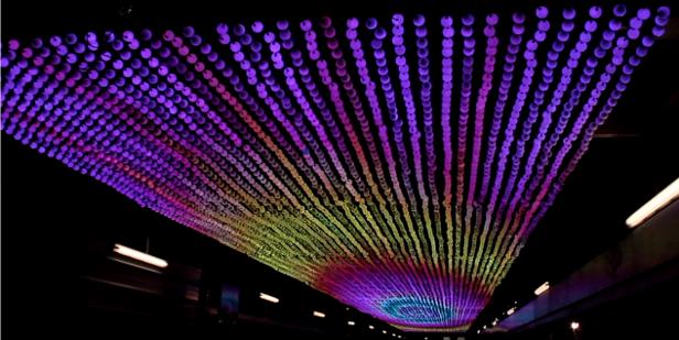
The french artist Fred Sapey-Triomphe has built a 42×4m screen at a temporary railway station in Belgium, for the Mons2015 festivities. With the 10cm pixel pitch, there are 420×40=16800 RGB LED that must be individually updated at 25Hz. 1.3MB/s must be distributed over 42m, which is not possible without Ethernet! The many power supplies create their own problems as well, particularly during power-up.
The screen is divided into 6 zones, each controlled by its own WizYasep board (fitted on a custom extension board). The available GPIO are allocated to more LED channels and to control Solid State Relays. Power sequencing greatly reduces the huge inrush current during power-up. The whole screen is made of 6×20=120 LED channels and 6×4=24 individual high voltage circuits, making the system modular and fault-tolerant. The videos are fluid and devoid of artefacts.
Each WizYasep board drives 20×140=2800 asynchronous RGB LED, or 8400 bytes. The 25Hz refresh rates requires a bandwidth of 210K bytes per second, which is well within the board's limits: a single channel's bandwidth is 100KB/s and 140 asynchronous LEDs can be refreshed 100000/(3×140)=230 times per second. 20 channels would need 20×100K=2MB/s, while the Wiznet interface has a 16b×9MHz=18MB/s peak bandwidth.
However, the 100BaseT saturates at about 10MB/s. The nanocomputer that manages the videos must not only send the data over the network, but also simultaneously read them from mass storage. The total bandwidth of 1.3MB/s of uncompressed data works well but starts to strain the cheap central computer. A larger and faster screen (50 or 100 frames/second) can be extrapolated and would require a faster computer with a Gigabit Ethernet port and a suitable hub to spread the individual, slower data streams.
Many small enhancements are planned to make this board easier to use and configure by newcomers. However, this is just an approximate roadmap and priorities might shift unexpectedly.
The Open Pixel Control protocol could be supported but the fine synchronisation would not be possible.
Users might be able to upload some pictures in the SPI Flash (a default or start screen for example) or read frames sequences from a SD card (adapter required).
The digital design is able to easily scale up to 40 channels (and probably more), but the existing version of the board can only provide 24 GPIO. A larger FPGA would be needed, on a new version of the board.
A more powerful FPGA could also remap the pixels on the fly. Currently, the order of the pixels must be computed before transmission over Ethernet...
Future versions might be reconfigured over the network, thanks to an integrated web server. The console port will remain available for factory programming, on-site reconfiguration, debugging and un-bricking. With enough onchip CPU resources, more protocols such as DHCP or Artnet could be supported.
Aside from driving LED screens, the WizYasep board could be re-purposed for:
- Transmission/Broadcast/Multicast of sound/music inside a building (the asynchronous LED module in the FPGA would be replaced by a SPDIF or I2S emitter).
- Electronics laboratory tools, displacing GPIB and USB (which require installation of drivers, which locks the tools to a specific platforms and exposes it to obsolescence risks). Many types of equipment could benefit: digital sampling oscilloscopes, logic analysers, SPI or JTAG programmers, ICE (In Circuit Emulation)... The HTTaP was indeed developped for this purpose.
- Remote control or presence, alarm/safety/security systems...
The WizYasep is currently being introduced after a successful pre-series, further batches will be manufactured if there is enough demand. The unit price, in the 200€ ballpark, will decrease with quantity and depending on delays or eventual design tweak requests. Please contact YGDES for a demonstration, a workshop or evaluation of your requirements.
The WizYasep's updates can be found on hackaday.io.
The WizYasep is also featured in the Wiznet Museum.
More insight in this interview.
Page created 20150225 par whygee@f-cpu.org
version 20150227
version 20150903
version 20150919